A hydraulic motor is a mechanical actuator that converts hydraulic pressure and flow into torque and angular displacement (rotation). The hydraulic motor is the rotary counterpart of the hydraulic cylinder as a linear actuator. Most broadly, the category of devices called hydraulic motors has sometimes included those that run on hydropower (namely, water engines and water motors) but in today's terminology the name usually refers more specifically to motors that use hydraulic fluid as part of closed hydraulic circuits in modern hydraulic machinery.
Conceptually, a hydraulic motor should be interchangeable with a hydraulic pump because it performs the opposite function - similar to the way a DC electric motor is theoretically interchangeable with a DC electrical generator. However, many hydraulic pumps cannot be used as hydraulic motors because they cannot be backdriven. Also, a hydraulic motor is usually designed for working pressure at both sides of the motor, whereas most hydraulic pumps rely on low pressure provided from the reservoir at the input side and would leak fluid when abused as a motor.
Conceptually, a hydraulic motor should be interchangeable with a hydraulic pump because it performs the opposite function - similar to the way a DC electric motor is theoretically interchangeable with a DC electrical generator. However, many hydraulic pumps cannot be used as hydraulic motors because they cannot be backdriven. Also, a hydraulic motor is usually designed for working pressure at both sides of the motor, whereas most hydraulic pumps rely on low pressure provided from the reservoir at the input side and would leak fluid when abused as a motor.

Vane motor
A vane motor consists of a housing with an eccentric bore, in which runs a rotor with vanes in it that slide in and out. The force differential created by the unbalanced force of the pressurized fluid on the vanes causes the rotor to spin in one direction. A critical element in vane motor design is how the vane tips are machined at the contact point between vane tip and motor housing. Several types of "lip" designs are used, and the main objective is to provide a tight seal between the inside of the motor housing and the vane, and at the same time to minimize wear and metal-to-metal contact.
Gear motors

Gear motor
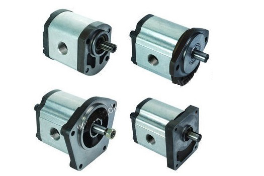
A gear motor (external gear) consists of two gears, the driven gear (attached to the output shaft by way of a key, etc.) and the idler gear. High pressure oil is ported into one side of the gears, where it flows around the periphery of the gears, between the gear tips and the wall housings in which it resides, to the outlet port. The gears then mesh, not allowing the oil from the outlet side to flow back to the inlet side. For lubrication, the gear motor uses a small amount of oil from the pressurized side of the gears, bleeds this through the (typically) hydrodynamic bearings, and vents the same oil either to the low pressure side of the gears, or through a dedicated drain port on the motor housing, which is usually connected to a line that vents the motor's case pressure to the system's reservoir. An especially positive attribute of the gear motor is that catastrophic breakdown is less common than in most other types of hydraulic motors. This is because the gears gradually wear down the housing and/or main bushings, reducing the volumetric efficiency of the motor gradually until it is all but useless. This often happens long before wear causes the unit to seize or break down.
A gear motor (external gear) consists of two gears, the driven gear (attached to the output shaft by way of a key, etc.) and the idler gear. High pressure oil is ported into one side of the gears, where it flows around the periphery of the gears, between the gear tips and the wall housings in which it resides, to the outlet port. The gears then mesh, not allowing the oil from the outlet side to flow back to the inlet side. For lubrication, the gear motor uses a small amount of oil from the pressurized side of the gears, bleeds this through the (typically) hydrodynamic bearings, and vents the same oil either to the low pressure side of the gears, or through a dedicated drain port on the motor housing, which is usually connected to a line that vents the motor's case pressure to the system's reservoir. An especially positive attribute of the gear motor is that catastrophic breakdown is less common than in most other types of hydraulic motors. This is because the gears gradually wear down the housing and/or main bushings, reducing the volumetric efficiency of the motor gradually until it is all but useless. This often happens long before wear causes the unit to seize or break down.

هیدروموتور دنده ای
مکانیزم و ساختمان داخلی اینگونه هیدروموتورها شبیه به پمپهای دندهای بوده و سرعت دورانی اینگونه پمپها بستگی مستقیم به میزان حجم ورودی سیال داشته و با تغییر در میزان این جریان سرعت آن تغییر پیدا میکند.
پس در نظر داشته باشید جهت کنترل سرعت چرخش از این امکان میتوان استفاده نمود.
هر چه سطح مقطع دندهها بزرگتر باشد یا به عبارتی دندهها بزرگتر باشد، نیروی گشتاور هیدروموتور بیشتر گردیده و سرعت آن کم میگردد که عکس این عمل نیز صادق میباشد.
اینگونه هیدروموتورها در توانهای مختلف ( توانهای هیدروموتورها را برحسب hp اسب بخار یا kw کیلووات میسنجند) در دسترس میباشد.
معمولاً حداکثر سرعت چرخش برحسب دور بر دقیقهی اینگونه هیدروموتورها ۱۰۰۰rpm بوده که جهت تبدیل به نیروهای بیشتر، شافت خروجی اینگونه هیدروموتورها مستقیماً به گیربکسهای کاهشدهنده سرعت و افزاینده قدرت نصب و از خروجی گیربکس جهت حرکتهای چرخشی مورداستفاده میگردد.
درصورتیکه بخواهیم بالانس هیدرولیکی ازنظر فشار در یک هیدروموتور ایجاد گردد معمولاً مسیری از قسمت خروجی به قسمت ورودی باز نموده که به این وسیله نیروهای فشاری قسمت کمفشار و پرفشار را در مقابل یکدیگر قرار داده که توسط آن بالانس هیدرولیکی ایجاد نموده و بتوان سرعت و قدرت یکنواخت ایجاد نمود.
هیدروموتور پره ای (تیغه ای یا کارتریجی)
عملکرد اینگونه هیدروموتورها (شکل زیر) تا حدود بسیار زیادی مشابه پمپهای پرهای میباشد که صفحهای دارای چندین شیار ( با توجه به نوع طراحی سازنده تعداد شیارها مشخص میگردد) که داخل هر شیار تیغههایی ( Blads ) که در پست آنها فنرهایی جهت هدایت تیغهها همیشه به سمت بیرون بهصورت خارج از مرکز داخل محفظهای نصب گردیده است، میباشد.
در هنگام ورود سیال از مجرای ورودی سیال، تیغهها را حول محور صفحه حرکت داده و هر چه صفحه در محفظهای که خارج از مرکز با صفحه هست، چرخش مینماید نیروی بیشتری به پرهها وارد گردیده و موجب چرخش سریعتر میگردد.
اینگونه هیدروموتورها معمولاً فقط به یک سمت (در جهت عقربههای ساعت و یا خلاف آن) تولید میگردند و درصورتیکه بخواهیم از دو طرف استفاده نماییم برای حفظ لوازم آببندی میبایست به توصیههای سازندهی آن توجه نماییم.
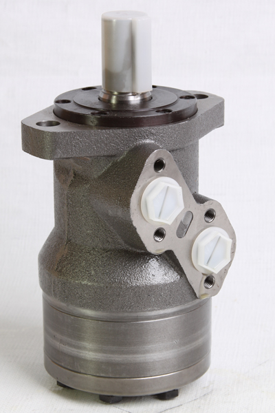
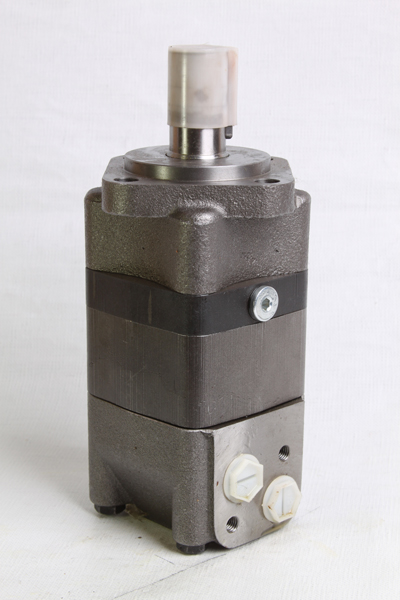
هیدروموتور ژیروتوری (اوربیتالی)
عملکرد اینگونه هیدروموتورها بهگونهای است که (بهصورت تئوری) دو چرخ دنده بهصورت خارج از مرکز داخل یکدیگر درگیر شده که ابتدا سیال ورودی وارد گردیده و موجبات چرخش شافت متصل به چرخدنده داخلی را ایجاد مینماید.
با توجه به اینکه گشتاور تولیدشدهی دندهی داخلی نسبت به دنده خارجی دارای تغییرات کمتری میباشد ، اینگونه هیدروموتورها را برای سرعتپایین مناسب نموده که از مشخصات اینگونه هیدروموتورها گشتاور نسباتا بالا و سرعتپایین ( Low-speed, high-torque motors ) بوده که در انتخاب و جایگزینی در مدارهای موردنظر میبایست موردتوجه قرار بگیرد.
هیدروموتورهای پیستونی
این هیدروموتورها به دودسته زیر تقسیم میشوند:
هیدروموتورهای پیستونی با جابجایی ثابت
ساختمان داخلی اینگونه هیدروموتورها بهگونهای است که تعدادی پیستون ( معمولاً تعداد پیستونها فرد میباشد) بر روی بلوک سیلندر نصب گردیده میزان گشتاور بهوسیلهی اعمال فشار سیال روی انتهای پیستونها که بهصورت رفتوبرگشت بر روی صفحه که با زاویهای زیر آن نصب گردیده واردشده و موجب چرخش بلوک سیلندر میگردد.
ساختمان داخلی اینگونه هیدروموتورها بهگونهای است که تعدادی پیستون ( معمولاً تعداد پیستونها فرد میباشد) بر روی بلوک سیلندر نصب گردیده میزان گشتاور بهوسیلهی اعمال فشار سیال روی انتهای پیستونها که بهصورت رفتوبرگشت بر روی صفحه که با زاویهای زیر آن نصب گردیده واردشده و موجب چرخش بلوک سیلندر میگردد.
این گشتاور همیشه به نسبت زاویهی صفحه زاویهدار تغییر مییابد.
این هیدروموتورها دارای گشتاورهای بالا ( توان خروجی بالا) و سرعت حداکثر ۵۰۰۰RPM و همچنین شتاب اولیه بالا با عمر نسبتاً بالا که به نسبت قیمت بالایی آن قابل توجیه اقتصادی هست، طراحی و ساخته میشود.
افزاش تعداد پیستونها در این هیدروموتورها باعث بالا رفتن گشتاور و کم شدن سرعت و همچنین نرم و یکنواخت شدن سرعت میگردد.
با توجه به اینکه ساختمان داخلی اینگونه هیدروموتور نسباتا پیچیده و دقیق هست جهت باز و تعمیر نمودن آن، گذراندن دورههای مخصوص لازم به نظر میآید.
از قابلیتهای بارز اینگونه هیدروموتورها امکان چرخش هیدروموتور در دو سمت چپ و راست با تعویض جریان عبوری سیال بهراحتی امکانپذیر هست.
معمولاً در اینگونه هیدروموتورها ، تعداد پیستونها ۹ عدد بوده که بر روی صفحه زاویهدار با زاویه ۱۵ درجه حرکت مینمایند.
هیدروموتورهای پیستونی با جابجایی متغیر
عملکرد اینگونه هیدروموتورها دقیقاً مطابق با هیدروموتورهای پیستونی با جابجایی ثابت بوده با این تفاوت که امکان تغییر زاویه صفحه زاویهدار زیر پیستونها وجود دارد که این زاویه معمولاً با تلورانس ۳۰ درجه ( ۱۵+ درجه ) نسبت به سطح افق قابلتغییر میباشد.
با تغییر زاویه صفحهی زاویهدار ، امکان تغییر سرعت که معمولاً این سرعت قابلکنترل تا حداکثر دور هیدروموتور یعنی ۵۰۰۰ RPM میباشد وجود دارد.
همیشه این چرخش با گشتاوری پایدار و قابلاطمینان که شتاب بسیار خوبی را به همراه دارد و امکان تغییر جهت از چپ به راست را برخوردار و در دسترس میباشند.
هیدروموتور پیستونی شعاعی
ساختمان داخلی اینگونه هیدروموتورها بهگونهای است که تعدادی پیستون ( معمولاً تعداد پیستونها فرد میباشد) بر روی شافت خروجی و بدنه موتور هیدرولیکی نصب گردیده میزان گشتاور بهوسیلهی اعمال فشار سیال روی انتهای پیستونها که بهصورت رفتوبرگشت بر روی یک کاور متصل به بدنه واردشده و موجب چرخش شافت خروجی میگردد.

